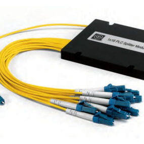
Pre-connectorized PLC Splitters
SENKO’s Pre-connectorized PLC Splitters are based on the Plasma Chemical Vapor Deposition (P-CVD) technology and its patented fabrication process for providing stable optical performance. SENKO’s Pre-connectorized PLC Splitters feature guaranteed performance specifications and high reliability that surpass Telcordia requirements and are tailored for different applications and markets.
- Low Insertion Loss
- Excellent Uniformity
- Broad Operating Wavelength
- Low Polarization Dependency
- High Maximum Power Tolerance
| PARAMETERS¹ | 1X2 | 2X2 | 1X4 | 2X4 | 1X8 | 2X8 | 1X16 | 2X16 | 1X32 | 2X32 | 1X64 |
|---|---|---|---|---|---|---|---|---|---|---|---|
| Operating Wavelength (nm) | 1260 ~1650 | ||||||||||
| Insertion Loss, Max. (dB) | 4.6 | 4.8 | 8 | 8.4 | 11.3 | 12.1 | 14.3 | 15.1 | 17.5 | 18.3 | 21.6 |
| Uniformity (dB) | 0.7 | 1.2 | 0.9 | 1.8 | 1.1 | 2.1 | 1.5 | 2.4 | 1.8 | 2.6 | 3.1 |
| PDL, Max. (dB) | 0.2 | 0.2 | 0.2 | 0.2 | 0.3 | 0.4 | 0.3 | 0.4 | 0.3 | 0.4 | 0.4 |
| WDL (dB) | 0.3 | 0.4 | 0.3 | 0.4 | 0.3 | 0.5 | 0.5 | 0.6 | 0.5 | 0.8 | 0.5 |
| Return Loss, Min. (dB) | UPC = 50 / APC = 55 | ||||||||||
| Directivity Min. (dB) | 55 | ||||||||||
| Operating Temp. (°C) | -30 ~ +70 | ||||||||||
| Dimensions (mm) | 7(W)x4(H)x60(L) | 12(W)x5(H)x80(L) | 12(W)x5(H)x60(L) | 12(W)x5(H)x80(L) | 12(W)x6(H)x80(L) | 20(W)x6(H)x100(L) | 40(W)x6(H)x100(L) | ||||
Notes:
1. Values taken at room temperature, 1310 and 1550nm, without connectors.
2. Custom specification are also available.
3. All types of SM fiber are available.
Configurations are available in various NxM configurations, with various connector options. Custom packaging is also available.
Datacom
Telecommunications
Local Area Networks (LAN)
Cable TV (CATV)
Local Convergence Points (LCP)
FTTx


A PLC splitter is an acronym for Planar Waveguide Circuit splitter. This technology is consider to be a passive optical device that can be configured with many input and output channels. It is used to divide input signals to multiple output signals uniformly. PLC splitters are commonly found in PON, Datacom, LAN, CATV, LCP, FTTx and more applications. PLC splitters provide a low-cost light distribution solution with high channels counts while maintain high stability and high reliability.
PLC splitters mimic semiconductor technology. The planar waveguide circuit technology consists of one chip and several optical arrays. The light travels into the input, and is then split across multiple paths. Depending on the output requirements, the splitting ratio can even reach 64 output channels. PLC splitters can either come in pigtail options for splicing, or in connectorized forms for easier deployment.
PLC splitters can be found in many passive optical network (PON) deployments. Commonly, a single fiber link from an Optical Line Terminal (OLT) is deployed and split across several channels to many Optical Network Terminals (ONT) . That signal is then taken and distributed to it’s destination for various FTTx situations.


