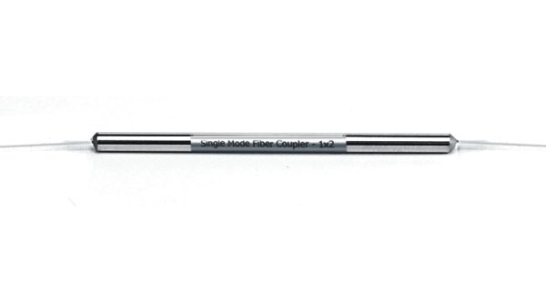
Single-mode Fiber Coupler 1×2 (50/50)
SENKO’s Single-mode Fiber Couplers are highly stable for multi-port optical signal splitting with low insertion loss. All devices are qualified according to industry standard test procedures.
- RoHS Compliant
- Compact packaging
- Stable and Reliable performance
| PARAMETERS | VALUES |
|---|---|
| Type | 1×2 |
| Coupling Ratio | 50/50 |
| Insertion loss Max. (dB)¹² | See below Table |
| Uniformity Max. (dB) | See below Table |
| Return Loss Min. (dB)² | 55 |
| Directivity Min. (dB) | 55 |
| PDL Max. (dB) | See below Table |
| WDL Max. (dB)³ | See below Table |
| TDL at -5~70°C Max. (dB) | 0.15 |
| Housing dimension | 250µm fiber 3.0mm (Ø) x 54mm (L) |
| 900µm tube 3.0mm (Ø) x 54mm (L) | |
| 2mm/3mm tube, ABS Box: 90mm(L)x20mm(W)x10mm(H) | |
| Fiber Type | SMF-28e 250µm bare fiber |
| Operating temperature (°C) | -40 ~ +85 |
| Storage temperature (°C) | -40 ~+85 |
| PARAMETERS | IL (dB) TYP. / MAX. | PDL (dB) MAX. | UNIFORMITY (dB) MAX. | WDL (dB) MAX. |
|---|---|---|---|---|
| Full Wavelength Band (1260~1620 nm) | 3.8 / 4.5 | 0.3 | 1.2 | NA |
| 3 Wavelength Band (1310/ 1550 ±40 and 1490 ±10 nm) | 3.4 / 3.7 | 0.2 | 0.8 | 0.5 |
| Dual Wavelength Band (1310/1550 ± 40 nm) | 3.3 / 3.6 | 0.15 | 0.7 | 0.3 |
| Single Wavelength Band (1310±40 or 1550 ±40 nm) | 3.2 / 3.4 | 0.15 | 0.6 | 0.2 |
Notes:
1. The specifications are not including connectors.
2. IL is worst case including PDL, TDL, and WDL.
3. WDL means IL change over Single wavelength band. Only for each window band, not including water peak band.
Network Monitoring
FTTH
Telecommunications


The fused biconical taper structures exhibits lower losses, allows arbitrary branching ratios, has polarization independence, and a broad range of operational wavelengths.
In a 1×2 fiber optic coupler each output is less than one-half of the power of the input signal which is around 3dB of loss per channel.
Splitters are common in telecommunication, network monitoring and FTTx applications. The WMD fused links are used in telecommunication and LAN applications.